
A PLC splitter ratio tells you how many outputs you get and how much light each one carries. Higher ratios serve more endpoints from one fiber, but every extra leg costs you signal.
Most buyers pick on port count alone. Then the loss budget comes up short and someone rolls a truck to fix it. Run the math first. Whether you’re specifying PLC splitters for an FTTH cabinet or a utility node, the process is the same. Here’s how it works.
What 1×2, 1×4, and 1×8 Actually Mean
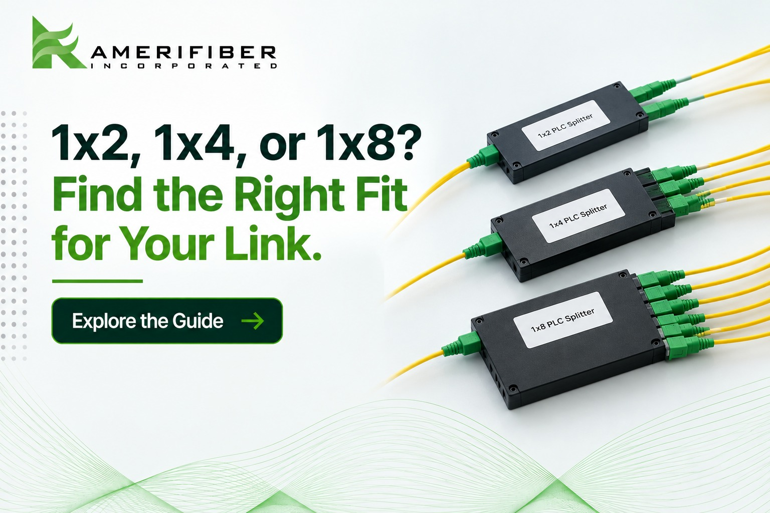
Read it as one input by N outputs. A 1×2 takes one fiber in and gives you two out. A 1×4 gives you four. A 1×8 gives you eight.
PLC stands for planar lightwave circuit. The splitting happens on a small glass chip, and it’s passive. No power. No electronics. The chip divides the light evenly across every output leg.
Here’s what even division looks like:
- 1×2: each output gets 50% of the light
- 1×4: each output gets 25%
- 1×8: each output gets 12.5%
In theory, every doubling of outputs costs 3 dB per leg: 3.0 dB for a 1×2, 6.0 for a 1×4, 9.0 for a 1×8. Real parts lose more. That gap drives every decision below. Your PLC splitter ratio is really a decision about how much signal you can afford to give away.
1×2 vs 1×4 vs 1×8 PLC Splitters: The Real Differences
| Ratio | Light per output | Typical max insertion loss* | Where it shows up |
| 1×2 | 50% | About 3.6 to 4.0 dB | Network taps, feeder splits, backup paths |
| 1×4 | 25% | About 7.1 to 7.4 dB | Small MDUs, cabinet nodes, business campuses |
| 1×8 | 12.5% | About 10.2 to 10.7 dB | Neighborhood distribution, FTTH cabinets |
*Typical maximums for standard singlemode PLC splitters. Loss varies by manufacturer, connector type, and wavelength, so check the spec sheet on your exact part.
1×2: The lowest loss of the three. Use it to feed two buildings off one run or to build a redundant path without hurting reach.
1×4: The middle ground. It fits a small MDU or a cabinet serving a handful of drops. You pay roughly double the loss of a 1×2 for twice the endpoints.
1×8: The workhorse for neighborhood distribution. It serves more homes per fiber, but about 10 dB is gone before the signal leaves the cabinet.
So which is best? None of them. The right PLC splitter ratio depends on how many endpoints you serve and how much loss you can spare, not on which number looks biggest.
How Split Ratio Hits Your Signal
The math says 3 dB per doubling. Real parts run higher because of excess loss from the chip, the pigtails, and the connectors. Expect real-world PLC splitter insertion loss to land roughly 0.6 to 1.7 dB above the ideal.
Go bigger and the loss climbs. A 1×16 runs about 13 to 14 dB. Amerifiber’s own 1×32 SC/APC splitter is rated at 17.10 dB maximum insertion loss with return loss above 60 dB.
Here’s a scenario. A GPON Class B+ link allows a maximum of 28 dB of path loss. You split 32 ways with a 1×4 feeding four 1x8s. Every path crosses both stages, so the splitters cost about 18 dB. Add a 10 km singlemode feeder at roughly 0.35 dB per km, so 3.5 dB. Add 2 dB for connectors and splices. That’s 23.5 dB, or 4.5 dB under the maximum. Hold back a 3 dB engineering reserve and you have 1.5 dB of real headroom. One dirty connector could use it up.
Always test your PLC splitter ratio against the full link, not just the splitter.
How to Choose the Right Split Ratio
Want to know how to choose a PLC splitter without guessing? Work through four checks in order.
- Loss budget. Subtract fiber loss, connectors, splices, and a safety margin of about 3 dB from your system budget. What’s left is what the splitter can spend.
- Endpoints. Count the drops you serve today. Then add what you’ll realistically build in the next few years.
- Architecture. Centralized splitting puts one high-ratio splitter, like a 1×32, in a single cabinet. It’s simpler to manage and test. Distributed splitting cascades stages, like the 1×4 and 1×8 above. It can cut distribution cable and lets you add capacity in steps, but you maintain more splitter locations. For the same 32 legs, cascading usually costs slightly more loss, since each stage adds its own excess loss.
- Connector and mounting. PON splitters commonly use APC polish for low back reflection, but connector types vary. Match the rest of your link, and don’t mate APC to UPC. Our guide to APC vs. UPC connectors covers the difference. For indoor builds, a 1RU rack mount splitter shelf keeps ports labeled and flush in a 19-inch rack.
Mistakes That Cost You a Truck Roll
Most of these trace back to one habit: picking the PLC splitter ratio before running the numbers.
- Mixing APC and UPC. The angle mismatch adds loss and hurts return loss.
- Ignoring excess loss. The math says 3 dB. The part says 4.
- Over-splitting for growth that never comes. Six homes on a 1×32 instead of a 1×8 burns about 6 dB of margin for nothing.
- Forgetting that cascades stack. Two stages means two sets of loss.
- Skipping the cleaning step. A dirty end face adds loss and reflections on its own.
When Stock Doesn’t Fit
Not every build fits a catalog. Maybe you need custom lead lengths, a different jacket color, or a connector mix that isn’t on the shelf. Amerifiber builds custom-built assemblies to order in the U.S., backed by 30+ years in the industry.
Talk It Through Before You Order
Still not sure which PLC splitter ratio fits your link? Send us your loss budget and endpoint count. An Amerifiber sales engineer will walk through the math with you and tell you straight if a smaller ratio does the job. No pitch. Just a second set of eyes before you order.
Contact Amerifiber and get the build spec’d right the first time.
FAQs
How does a PLC splitter work?
A PLC splitter uses a planar lightwave circuit, a small chip with waveguides etched into glass, to divide one optical signal into equal parts. It’s passive, so it needs no power. Each output carries the same share of light, minus a small amount of loss.
Is a 1×4 PLC splitter better than a 1×2?
Neither is better. A 1×4 serves more endpoints but loses about 7 dB, versus about 4 dB for a 1×2. Choose based on how many endpoints you need and how much loss you can afford.
Can I use multiple PLC splitters together?
Yes. Cascading is common, such as a 1×4 feeding four 1×8 splitters. Losses add up at each stage, so add every splitter’s insertion loss to your link budget.
What’s the difference between active and passive splitters?
Optical splitters, including PLC splitters, are passive. They divide light with no power and no electronics. “Active” usually means powered equipment in the path, like a switch or media converter, that regenerates the signal. PON builds use passive splitters in the field. Active Ethernet puts powered gear at the node instead.
Why does the split ratio matter?
It sets how many endpoints one fiber can serve and how much signal each one gets. A higher ratio serves more endpoints but leaves less loss budget for the fiber run.