
Highlights
- ORL measures the amount of light reflected back toward the source in a fiber optic system—higher ORL (in dB) means less reflection and better performance.
- Poor ORL is commonly caused by dirty connectors, poor splices, mismatched connector types, or damaged fibers.
- ORL is measured using ORL meters or OTDRs, and it’s critical for maintaining signal quality in FTTH, CATV, DWDM, and high-speed networks.
- Recommended ORL values range from >26 dB (FTTH) to >45 dB (DWDM), depending on the application.
- You can improve ORL by cleaning connectors, using APC terminations, avoiding UPC/APC mismatches, and following proper installation practices.
Why ORL Matters in Fiber Optics
Optical networks are the backbone of modern communication, supporting vast amounts of data transmission daily. Optical Return Loss (ORL) plays a critical role in ensuring these networks are efficient, reliable, and capable of meeting the demands of high-speed connectivity. By understanding and managing ORL, professionals can enhance network performance, reduce downtime, and ensure a seamless end-user experience.
Defining ORL (Optical Return Loss)
ORL is the measure of light reflected back toward the source in an optical fiber system. It’s expressed in decibels (dB), where higher ORL values signify lower reflection and better overall signal quality. This property is essential for maintaining signal integrity and avoiding disruptions in optical communication systems.
Impact on Network Performance
Reflections within an optical link aren’t just minor hiccups—they can lead to serious network issues. Excessive reflections interfere with laser transmitters, leading to signal degradation and higher bit error rates (BER). For applications like high-speed digital networks, FTTH (Fiber to the Home), DWDM (Dense Wavelength Division Multiplexing), and CATV (Cable Television), managing ORL is not optional—it’s critical to achieve optimal performance and customer satisfaction.
ORL vs. Reflectance
At first glance, ORL and reflectance might seem interchangeable, but they’re distinct measures. ORL quantifies the total back-reflected light across the entire fiber link, delivering a holistic overview. Reflectance, on the other hand, zeroes in on specific points—like connectors or splices—where light reflection occurs. Both are crucial for diagnosing network health, but their applications differ when evaluating and troubleshooting fiber optic systems.
What Causes ORL in Fiber Optic Networks?
Optical Return Loss (ORL) is a critical factor in fiber optic networks, as it directly impacts signal integrity and network performance. ORL refers to the portion of light that reflects back toward the source due to imperfections or inconsistencies along the optical path. While it’s natural to have some level of reflection, excessive ORL can degrade signal quality and cause network inefficiencies.
Common Sources of Reflection
- Poor connector end-face quality or contamination
- Air gaps between connectors
- Mechanical splices with mismatched cores
- Breaks or microbends in the fiber
Each of these factors disrupts the intended flow of light, creating unnecessary reflections that increase ORL and negatively affect performance.
Examples of High-ORL Scenarios
To illustrate these challenges, consider these situations where ORL frequently becomes problematic:
- Dirty SC connectors in a patch panel
- Improperly mated APC connectors with UPC types
- Unused ports left open without dust caps
These seemingly minor issues can lead to significant reflectance, making it crucial to adhere to best practices in handling and maintenance.
The Role of Connectors and Termination Quality
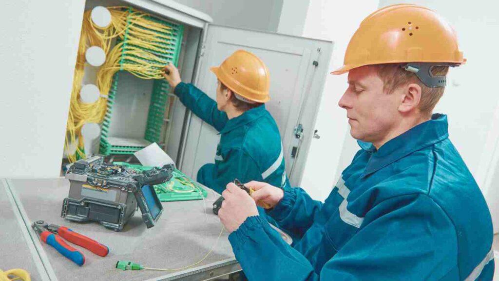
The quality of connectors and terminations plays a pivotal role in minimizing ORL. For example, APC connectors are specifically designed to reduce reflectance by angling the end-face. However, their effectiveness depends on proper polishing, alignment, and cleanliness. A high-quality termination ensures that light travels efficiently, reducing reflections that lead to ORL, and ultimately, maintaining the reliability of your network.
ORL Measurement – Tools, Methods, and Standards
How ORL Is Measured
Optical Return Loss (ORL) is measured using specialized equipment like an ORL meter or by employing an OTDR (Optical Time Domain Reflectometer) for analysis. Measurements are expressed in decibels (dB), with values typically 35 dB or higher being considered acceptable for most modern fiber optic applications.
The ORL value indicates the level of reflected light returning toward the signal source. Lower reflected light results in better ORL values, signifying higher link efficiency and reduced noise interference. Accurate measurement is vital for ensuring network reliability, especially in high-speed data communications.
Key Tools for ORL Testing
Testing ORL requires precise instrumentation to capture reflections and evaluate link performance. Key tools include:
- Optical Return Loss Meters – Specialized devices designed specifically for ORL measurement, yielding fast and reliable readings.
- OTDRs with ORL Measurement Capabilities – Multi-functional tools that can trace fiber integrity and measure return loss.
- Optical Power Meters – Used for complementary loss measurements, ensuring comprehensive verification of the optical link.
Testing Example (Step-by-Step)
Conducting an ORL test typically follows these steps for consistency and accuracy:
- Connect the test jumper from the ORL meter to the device under test, ensuring proper alignment and clean connections.
- Zero out the system to eliminate any baseline inaccuracies and calibrate for the test environment.
- Perform the measurement, allowing the meter or OTDR to calculate the return loss.
- Compare results against industry standards and application-specific thresholds. For instance, 40 dB or greater is ideal for high-speed connections.
Relevant Industry Standards
Several industry standards provide guidance and minimum requirements for ORL in fiber optic systems. Adherence to these standards ensures compatibility, performance, and reliability:
- TIA-568 and IEC 61300-3-6 – These standards define acceptable return loss levels for connector and link performance.
- Service-specific requirements, such as those for GPON or 10G Ethernet, often demand ORL to exceed 26 dB, with better performance expected for more advanced or longer-distance links.
Understanding and following these guidelines plays a critical role in meeting customer demands for a high-performing and future-proof network.
ORL Thresholds and What They Mean
Optical Return Loss (ORL) is a critical metric in fiber optics network, directly influencing signal integrity and overall system performance. ORL measures the amount of optical signal reflected back toward the source from various points in the network. High ORL values suggest minimal signal reflection, which ensures smoother data transmission and reduces error rates. Conversely, poor ORL can degrade transmission quality, leading to network instability and unreliable connectivity. Understanding ORL thresholds is vital for ensuring your network operates at its best.
Ideal ORL Values by Application
Different applications demand varying levels of ORL to meet performance and reliability standards. Here’s a quick breakdown:
- FTTH (GPON): >26 dB
These networks can tolerate moderate ORL levels but require stability to maintain end-user satisfaction.
- Enterprise LANs: >30 dB
Enterprise environments prioritize reliability—keeping ORL above this threshold ensures consistent operations.
- CATV: >40 dB
Cable television networks operate on finer tolerances, requiring stringent control over reflections.
- DWDM/High-speed links: >45 dB
Dense Wavelength Division Multiplexing and ultra-high-speed connections demand nearly immaculate ORL to maximize data transmission efficiency.
Troubleshooting Poor ORL
When ORL drops below acceptable thresholds, taking decisive steps can restore network performance. Here’s how to address common issues:
- Inspect and clean connectors
Dust and debris often cause unwanted reflections. A simple cleaning may resolve the issue entirely.
- Use angled (APC) connectors where appropriate
APC connectors offer superior performance by minimizing back reflections.
- Re-terminate faulty splices
Ensure splices are executed with precision to reduce unnecessary signal reflection at junctions.
- Use proper dust caps and inspect for physical damage
Protect components and regularly check for cracks, scratches, or other visible defects.
Proactive ORL Management
Staying ahead of ORL issues relies on consistent, preventive strategies. Proactivity here translates into long-term network health:
- Incorporate ORL testing in regular maintenance
Don’t wait for issues to arise—test early and often to catch problems before they escalate.
- Document ORL values across key network segments
Keeping clear historic records allows for easier trend analysis and quicker diagnostics.
- Educate field techs on return loss best practices
Ensure teams are equipped to identify, troubleshoot, and prevent ORL issues confidently.
ORL management is non-negotiable in modern fiber optic systems. By understanding how to measure, troubleshoot, and maintain optimal ORL, you can sustain a robust, high-capacity network that supports both present and future demands effectively.
ORL and Fiber Design – Engineering for Low Reflection
Optical Return Loss (ORL) is a critical factor in fiber optic system performance. It refers to the amount of light reflected back toward the source due to discontinuities or imperfections in the optical path. High ORL can disrupt signals, degrade system reliability, and impact high-speed data transmission. Designing fiber networks with low reflection ensures optimized performance, especially in today’s advanced, high-bandwidth applications.
Choosing the Right Connector Type
The connector type plays a vital role in controlling ORL and overall link quality. Choosing the appropriate connector ensures that system losses and reflections are minimized.
- UPC (Ultra Physical Contact) connectors are ideal for low insertion loss. They create a solid connection, enabling efficient light transfer while slightly limiting reflection.
- APC (Angled Physical Contact) connectors are designed to minimize reflectance drastically, achieving superior performance in minimizing ORL.
- Avoid mixing APC and UPC connectors in the same optical link—it can lead to high losses and signal distortion. Always ensure consistent connector types across the system for the best results.
Best Practices for Minimizing ORL
Maintaining low ORL throughout the network requires adherence to several best practices:
- Always clean before connecting – Dirt and debris at connection points can increase reflectance. Use industry-recommended cleaning tools to maintain a pristine optical surface.
- Opt for fusion splicing – Fusion splicing offers lower loss and decreased reflectance compared to mechanical splicing, making it the preferred method in critical deployments.
- Install connectors with precision polishing – Ensure connectors have verified geometry and meet industry-defined polishing standards to reduce reflection risks.
When to Use Angled Connectors
For certain systems, angled connectors are indispensable. They excel in applications with tight power budgets or stringent ORL requirements.
- Deploy APC connectors in high-bandwidth systems such as DWDM or RF video distribution, where low reflectance is crucial for maintaining signal integrity.
- When ORL specifications surpass 40 dB, angled connectors are your best ally to safeguard system performance.
By integrating these principles into your fiber optic network design, you’ll maintain system reliability while meeting the rigorous demands of modern data transmission.
Key Takeaways
- ORL (Optical Return Loss) is a critical measurement that impacts signal strength, quality, and equipment life in fiber optic networks.
- It measures total light reflected back toward the source and should be as high as possible in dB (indicating low reflection).
- ORL can be affected by connector quality, contamination, poor splicing, and mismatched components.
- Testing tools like ORL meters and OTDRs are essential for diagnosing and maintaining low-ORL systems.
- Use of clean APC connectors, proper termination techniques, and routine testing can drastically reduce ORL and improve long-term performance.
Frequently Asked Questions
1. What does ORL stand for and what does it measure?
ORL stands for Optical Return Loss. It measures the amount of light that is reflected back toward the source in a fiber optic network. A higher ORL value (in dB) indicates less reflected light, which means a cleaner, more efficient connection.
2. How is ORL different from reflectance?
ORL measures the total cumulative reflected light over the entire fiber link, while reflectance refers to the reflection at a specific point, such as a connector or a splice. Both are important, but ORL gives a broader picture of signal quality.
3. What causes poor ORL (high reflection) in fiber networks?
Common causes include:
- Dirty or poorly polished connectors
- Mismatched connector types (e.g., APC to UPC)
- Air gaps in mechanical splices
- Broken or cracked fiber ends
Maintaining proper cleaning, splicing, and termination practices can minimize these issues.
4. What is considered a good ORL value?
Acceptable ORL thresholds vary by application:
- >26 dB for FTTH and GPON
- >30 dB for enterprise/LAN
- >40 dB for CATV
- >45 dB for DWDM or high-speed data links
The higher the dB, the better the return loss (less reflected light).
5. How is ORL measured in the field?
Technicians measure ORL using:
- A dedicated ORL meter, or
- An OTDR (Optical Time Domain Reflectometer) with ORL testing capabilities
These tools help identify and localize reflective faults in the fiber link.
6. Can ORL affect signal performance or damage equipment?
Yes. Excessive ORL can interfere with laser transmitters, increase bit error rates (BER), and degrade overall network performance. Over time, it can also reduce the lifespan of sensitive optical components.
7. How can I improve ORL in my fiber network?
- Always clean connectors before connecting
- Use angled connectors (APC) for applications needing ultra-low reflectance
- Avoid mixing APC and UPC interfaces
- Ensure high-quality splicing and termination
- Include ORL measurement in routine network maintenance